|
ntroduction to Digital Magnetic
Recording
Rodolfo
Baggio
IBM Customer Executives Briefing Center
Mainz, Germany, October, 1986
Table of contents
1 - Introduction
2 - Principles of magnetics
3 - Digital magnetic recording
- Magnetic materials
- Writing
- Reading
- Pulse superposition
4 - Conclusion
5 - Bibliography
1 - Introduction
The search for ways to store information on an external device
at higher densities, and for retrieving it with higher speeds is one of the
most important challenges of research in computer science.
Storage devices are complex and their design involves the
knowledge of many different technologies, from magnetics to electronics, from
chemistry to aerodynamics.
The basic technology for the most used storage device is digital
magnetic recording. This is a special application of the magnetic recording
technology which was originally developed to record and reproduce sound. In
this case, the main requirement is to have a good similitude between the input
and output of a continuous waveform signal, therefore the frequency response
characteristics are the major concern of a designer of such systems.
In a digital storage device, the major concerns are (besides
the cost):
- density of information (number of bits in a unit length,
usually measured in bits per inch and tracks per inch)
- access time (the time needed to position the read and write
mechanism in a given position)
- data transfer rate (number of bits transferred in a unit
of time)
The most important of these parameters is the density due
to the influence it has on the others. For example, data transfer is directly
proportional to linear density while access time (seek time) is inversely
proportional to track density.
Magnetic recording is based on the interaction between a magnetic
storage medium and a magnetic transducer in relative motion with respect to
one another. The relative motion is usually obtained by moving the medium.
The magnetic field generated by the transducer (head), a small
electromagnet, magnetises in a permanent way a small region of the material.
By changing the direction of the current in the coil of the electromagnet,
it is possible to generate two different directions in the magnetic field
induced on the surface. These two different states are what we need to "write"
two different bits.
Conversely, when one of the tiny magnetised regions passes
under the head, an electrical pulse is induced in the coil of the electromagnet.
The pulse detected is proportional to the rate of change of the magnetic flux
and the direction of the current depends on the direction of magnetisation
in the region of the surface. In this way it is possible to "read" back the
different magnetic states written on the storage medium and to interpret them
as different bits.
In the so called longitudinal recording, the principal direction
of magnetisation is in the plane of the surface, parallel to the direction
of the motion. The path generated by the transducer on the surface, also parallel
to the direction of motion, is called a track.
The following characteristics of the materials involved are
of major importance to magnetic recording:
- the storage layer must be capable of retaining in a stable
way a sequence of permanent magnetic states
- the recorded pattern can be modified only by erasing or
rewriting (changing the magnetised state)
- the head is a device that has the basic functions of providing
a confined and intense magnetic field in order to magnetise a small region
of the material (writing process) and of producing a detectable electrical
pulse when passing by a magnetic flux arising from a magnetised state of
the storage medium (reading process).
Therefore, the recording surface is made of a high permeability
magnetic material, i.e. it is able to have a good "response" to a magnetic
field, and the head is an electromagnet, made with a coil winding and a magnetic
core with a gap.
In order to achieve high recording densities, it is necessary
to write a binary bit in the smallest possible space, and to place the bits
as close as possible. To be successful in this, the interactions and the relationships
between head and surface are extremely important. Since it is not possible
to focus magnetic fields like light, the only possibility to produce intense
and confined magnetic fields and to record dense bits, is to have narrower
gaps in the electromagnet, smaller spacings between head and medium, thinner
layers and higher speed of relative motion. In addition to that, narrower
pole tips will determine higher track density.
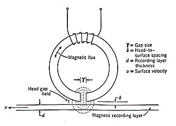
Fig. 1.1
The good balance of these parameters (shown in fig. 1.1) is
the most important and delicate task for the success of the whole process.
In magnetic recording, the writing process is not, as one
might think, the most critical.
As a matter of fact it is possible to write bits at higher
density than they can be read and converted into a detectable signal by appropriate
electronics.
Writing is done by the trailing edge of the magnetic field
generated by the head. For reading the entire magnetic field of the stored
bit is used to induce an electrical pulse in the reading head, and this pulse
must be able to give a large signal to noise voltage in order to be easily
and clearly converted into a digital form.
The main limiting factor is the distortion of the signal produced
by the closely packed bits. If the packing factor is too high (bit crowding),
the magnetic field detected is the overlap of the fields from the adjacent
bits. The total field sensed by the reading head gives, in this case, an induced
signal with a shape different from that produced by a single bit, thus leading
to the impossibility to interpret the recorded pattern in a correct way.
2 - Principles of magnetics
It may be useful to recall some of the concepts of magnetics.
In this part the concepts and the relationships are reviewed, the more important
to understand the digital recording processes well.
The interactions between electric currents and magnetic forces
were discovered and explained in the first half of 17th century. From these
researches it was found that a piece of magnetic material experiences a force
when it is put in a region in which there is a presence of an electrical current.
In this region a magnetic field is generated by the current. If the conductor
is linear, of infinite length and the current flowing has intensity i, the
value of the magnetic field B is given by:
B = k i / r
where r is the distance from the conductor.
In the CGS system of units, B is measured in Gauss.
In other words, the field B is proportional (k is a constant
of proportionality) to the intensity of the current and is inversely proportional
to the distance. If we have a circular turn of radius R, the field, in the
space external to the loop, at a distance r, is:
B = k i a / ( r2 + R2)3/2
(a = area of the loop).
For an infinite linear coil (solenoid), made of N turns, the
field in a point internal to the solenoid, has the value:
B = k 4p N
i
if the coil is circular (toroid):
B = k N i / r
r is the toroid internal radius.
All of these examples show that the magnetic field, due to
an electrical current, depends only on the intensity of the current and on
some geometrical characteristic of the circuit.
Since it is not possible to "see" a field of forces, whatever
they are, magnetic, gravitational, electrical etc., we use a graphical representation
for it. We draw the so called field lines, these lines represent the trajectories
of a particle or a piece of material that experiences the forces of the field.
The force is always tangent to the lines, their density is proportional to
the strength of the field.
The similarity between magnetic fields generated by currents
and by magnetic materials may be seen in fig. 2.1, where the field lines are
drawn for a magnetic needle and a solenoid.
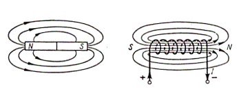
Fig. 2.1
If a current produces a magnetic field, we should expect that
a magnetic field is able, in some way, to give rise to an electrical current.
We can define the flux F of
B on a surface s as the product between these two quantities:
F =
B s
The basic relation, known as Faraday's law, linking B to an
electrical current is:
E = k D F / D t
i.e. any variation in time of a magnetic flux, produces a
voltage pulse. This relation may also be written as :
E = k v D F / D x
that means that a pulse is also produced in a conductor every
time there is a moving magnetic field (with speed v).
This is the principle on which a dynamo works. A conductor,
usually a coil, is moved with a certain speed in a region where a magnetic
field exists.
Let us take a coil, and put a piece of material inside. The
field outside is described by the equations above, but what is about the magnetic
field inside the material? In this case the magnetic field generated by the
current flowing in the coil will interact with the electronic currents inside
the material, as a result we shall find some difference in the magnetic field
inside. For historical reasons the field due to a magnetic material has a
different name, this one, the field H, is related to B by:
B = m H
H is measured in Oersted, the quantity m is called magnetic permeability, in vacuum (or in air) m = 1 , so no difference exists in this case, B and H have the same behaviour.
In any other material m is a complex function
and it depends on the material and on the field applied to it. The difference
between the fields B and H inside a piece of magnetically active material
is shown in Fig. 2.2.
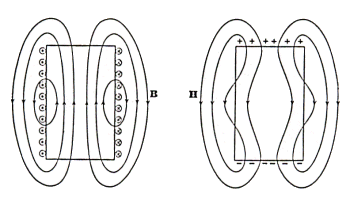
Fig. 2.2
From a physical point of view, the permeability of a magnetic
material is similar to the conductivity of an electric conductor, the higher
it is, the bigger will be the magnetic properties of the material. Substances
for which m ~ 1 show very small or no magnetic
properties, they are called amagnetic materials.
Usually, the permeability, for a specific material, is given
related to the permeability of vacuum. Being a ratio, m (r) (relative permeability), is a pure number.
If m is close to 1 (the magnetic
properties of the material are not too big) we call these substances paramagnetic
if m > 1, diamagnetic
if m < 1.
From a magnetic point of view, a material is interesting only
if it has good properties, this is the case of the ferromagnetic materials,
in which m >>
1.
Since the permeability is not a constant, in a ferromagnetic
material the relation between B and H is not a linear relation. Figure 2.3
shows this relation, the curve is known as hysteresis loop.
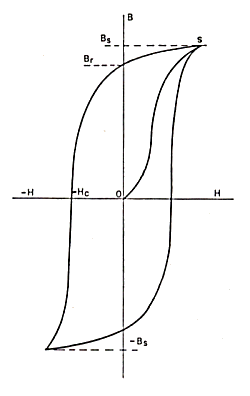
Fig. 2.3
Let us consider a piece of ferromagnetic material wound with
a coil.
At the beginning H = 0 and B = 0. Increasing H (increasing
the current in the coil), B increases in the way shown by the curve O-S up
to a value Bs, this is called saturation value, i.e. from now on, even big
increases in H will result only in insignificant increases in B. The material
is fully magnetised. If now H is decreased, B decreases along the curve S-Br.
The important thing is that when H reaches 0, B is not zero, but has the value
Br (residual magnetisation). This means that the material preserves now a
magnetisation even in absence of an external field, if there are no external
interferences, the magnetisation is permanent. In order to annul the field
B, we must apply a negative field -Hc, called coercive field, inverting the
current in the coil. The negative part of the loop is symmetrical to the positive
one.
The behaviour of permeability is shown in fig. 2.4. Its value
is related to the slope of the hysteresis curve, while H is increasing, m goes from an initial value to a maximum and then decreases when the B-H curve
flattens.
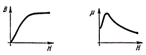
Fig. 2.4
It took a long time before a fully understanding of this phenomenon
was reached. We may now think of a ferromagnetic substance as composed of
small domains. In normal conditions, in the absence of external field these
domains are randomly oriented, so that on the average the total magnetisation
is zero. An external field H will produce a progressive orientation of the
domains along the field direction as long as its intensity is increasing.
A saturation will occur when all the domains are aligned with H. To destroy
this alignment we need a magnetic field with an opposite direction, and an
intermediate intensity between zero and the saturation value.
The coercivity (the value of the coercive field) is an important
physical parameter, it represents the "inertia" that a ferromagnetic substance
has, with regards to a magnetic field. A low coercivity means that the material's
magnetisation can easily be changed. Low coercivity materials are often called
soft magnetic materials, high coercivity are called hard materials. The hysteresis
loops in these two cases are shown in Fig. 2.5.
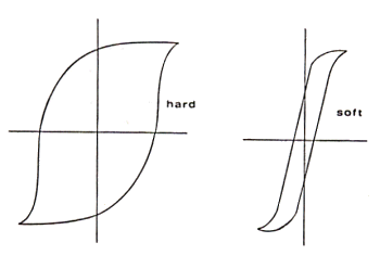
Fig. 2.5
When different materials are present, the magnetic flux tends
to confine itself in a high permeability path, in the same way that an electrical
current tends to flow in a high conductivity path. Given this analogy, we
may speak of magnetic circuits as well as of electrical circuits. An example
is shown in Fig. 2.6, along with its electrical equivalent.
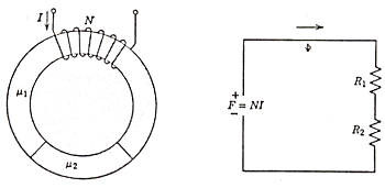
Fig. 2.6
The magnetic flux linking the circuit is:
F =
B s
where s is the cross sectional area of the toroid.
If m 1 and m 2 are
large, the flux will "flow" in the toroid, along it. Since the lines of flux
are continuous:
B1 = B2 or m 1H1 = m 2H2
We also have (see the expression above for the field of a
toroid):
H1 l1 + H2 l2 = N i
where l1 and l2 are the length of the
materials with m 1 and m 2 ,
N is the number of turns and i is the current flowing in the coil.
We can define a magnetomotive force F = N i, and a reluctance
R = F / F
That is R = H l / B s , or R = l / m s (since: B = m H) , with a perfect analogy
with the definition of the resistance: R = l / s s (s is the specific conductivity). Thus we
have in the magnetic circuit:
F = F1 + F2 = (R1 + R2) F
To complete the analogy, F, which is measured in ampere-turns,
may be interpreted as a voltage source, or electromotive force.
If one of the materials is air, i.e. there is a gap in the
toroid, whose permeability is one, the total reluctance of the circuit is
( m (air) = 1):
R = (l1 / m 1 s) + (l2 / s)
The reluctance depends only on the geometrical dimensions
of the gap. The magnetic field is divided in the circuit according to the
reluctances of the various parts, since m 1 >> 1 (ferromagnetic
material), H will tend to "concentrate" itself in the low
permeability portion of the circuit, and to "expand" outside the air gap.
If the gap is filled with an amagnetic but conducting material, electronic
currents will arise in it as consequence of a magnetic flux variation. These
currents will give rise to a magnetic field that will reinforce the tendency
to expand out of the gap (Fig. 2.7).

Fig. 2.7
3 - Digital magnetic recording
In theory it is possible to fully explain the behaviour and
the characteristics of a digital device from the principles and the formulas
we have seen in the previous chapter. Practically this task is quite impossible.
We introduced a lot of simplifications and, in order to understand the main
concepts, we made many assumptions that are not to be found in the real physical
world. The real world, especially when dealing with magnetic and electric
phenomena, is very complex. Magnetic properties are highly non linear and
many different parameters affect the magnetic behaviour in several ways. Our
main objective is to understand and to explain the basic concepts of digital
magnetic recording. To do so we still need to make some approximations and
to introduce restrictive hypotheses, but we also need to introduce some new
parameters and to examine, at least from a conceptual point of view, their
mutual interactions.
The basic situation we want to describe is shown in figure
3.1.
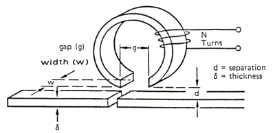
Fig. 3.1
Magnetic materials
Before examining this situation, let us say a few words about
the materials used in a storage device. From the considerations made in the
introduction on the principles of operation of magnetic recording and from
the fundamentals of the magnetic theory we are able to better specify the
main characteristics of the ideal materials we should need.
We have seen that the small electromagnet that forms a read/write
head must be able to produce a very intense and spatially well confined magnetic
field. In order to write densely packed bits, it must be possible to change
the direction of this field with a high frequency. In other words, we should
succeed in inverting the magnetisation of the head in a very short period
of time.
With these requirements we are describing a "soft" magnetic
material, with high relative permeability and high saturation magnetisation.
Moreover, the need for high frequency inversions in magnetisation may be stated
as a request for low coercivity and relatively low residual magnetisation
(remanence). Table 3.1 gives the values for some of the materials matching
these characteristics.
Table 3.1
Name and composition |
Permeability |
Coercivity |
Saturation |
| |
init. |
max |
Hc (Oe) |
Bs (G) |
Permalloy
(79Ni,17Fe,4Mo) |
20000 |
100000 |
0.05 |
8700 |
Mu-Metal
(77Ni,16Fe,5Cu,2Cr) |
30000 |
100000 |
0.02 |
7500 |
Ferrites |
|
|
|
|
|
Ni - Zn
|
2000 |
2000 |
0.15 |
3000 |
|
Mn - Zn
|
2-10000 |
5-20000 |
0.002-0.005 |
4-6000 |
On the other hand, the medium on which we record data must
be able to retain permanently the information stored at high density. That
is to say that we need a ferromagnetic material with high permeability in
which the magnetic domains are very small in order to be able to magnetise
tiny regions with different orientation. This is usually obtained by coating
a non magnetic substrate (usually aluminium) with a mixture made of an inert
material used as a binder (for example epoxy resins), in which are imbedded
small particles of the ferromagnetic substance. The magnetisation is preserved,
in absence of external forces, if the material has high coercivity and high
remanence. Finally, if the saturation field is not too high, i.e. it is relatively
"easy" to magnetise the material, we have the ideal medium to record information.
Table 3.2 gives the characteristical values for some of the materials currently
used.
Table 3.2
Name and composition |
Coercivity |
Remanence |
Saturation |
| |
Hc (Oe) |
Br (G) |
Bs (G) |
Iron Oxide
(g Fe2O3) |
200-350 |
1100-1300 |
4300 |
Chromium Dioxide
(CrO2) |
300-700 |
1600 |
6000 |
Cobalt film |
900 |
15000 |
18000 |
It is worth noting that all the values given in the tables
above are average and indicative only. The actual values depend on the mechanical
and thermal treatments the material receives during the fabrication. For a
coating substance, for example, the magnetic properties depend on the size
and the shape of the particles used, on their density and on their orientation
on the surface, on the methods used to finish the surface etc. There is no
theory able to predict the influence of all of these parameters, only direct
measurements after different trials may show which result is the best.
Writing
Let us now examine the two fundamental processes of digital
magnetic recording: writing and reading. The best way to understand a physical
phenomenon would be to have an analytical expression that describes it. In
other words, a formula in which all of the parameters of interest for some
process are contained, and the mathematical relations among them are completely
defined, would allow us to explain in a simple way, no matter how complex
the formula is, every possible behaviour and dependency of the parameters
of the process we are investigating. In the case of the writing of magnetic
information, we are facing a magnetic field generated by an electromagnet,
made with certain materials, having certain geometrical, electrical and magnetic
properties. Therefore we are looking for an expression relating quantities
like geometry of the head, number of turns in the coil, flying height, current
intensity etc. to give the intensity of the field produced and its form in
the space outside the head. Unfortunately this expression does not exist.
We need to introduce simplifications and approximations to
derive a meaningful relation, and, usually, the validity of such expressions
is proportional to the number and the type of hypotheses we make. The type
of hypotheses is defined by the objective we have in deriving the formula.
In the present instance, we are mainly interested in understanding
the role played by the several quantities, and in being able to predict, at
least roughly, how the resulting field is affected by changing one or more
of those parameters.
A useful description of this kind was given by O. Karlquist.
The approximations introduced are the following: the head (fig. 3.2) has infinite
length, with a gap of width g and the pole faces are parallel to the recording
medium. The relative permeability of the core is infinite and the field produced
is uniform across the gap. The latter is the major departure from the real
case (also shown in fig. 3.2), but it is a good approximation for small gaps
and for distances up to about g/3, that is a situation close to the real case.
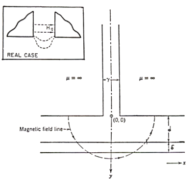
Fig. 3.2
The expression that gives the field H generated by such head
in the point (0,0) (in the gap) is:
Hg = N i / g
If we want to evaluate a real case, we need to introduce a
quantity called head write efficiency a w. This is defined as the ratio between the total
magnetomotive force (the product N i) of the head and that of the coil. It
is assumed that an air gap may lead to some losses.
The value for a w is:
a w = N i - D N i / N i = 1 - D N i / N i
The field is then:
Hg = 4p a w 10-3 N i / g (Oe)
with i in Amp and g in meters (in the next part we shall define
a read efficiency as well, which is easier to calculate for practical purposes).
The field lines for H (fig 3.2), since it is uniform and given
the geometry of the configuration, are semicircles with the center in the
point (0,0). The expression for the intensity of the field in any other point
below the gap is more complex and is given in graphical form in fig. 3.3,
splitting the components of H along the x and y axes.
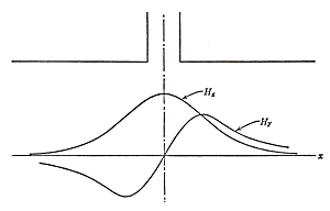
Fig. 3.3
It is possible to derive a simple relation for the field intensity
on the points on the axis of the gap, at distance y from it:
H(0,y) = 2 Hg / p tan-1 (g/2y)
At the bottom of the coating the distance is the sum of the
flying height (separation d) and the coating thickness (d ), y = d + d , in this point H has the value:
H(0,d+d ) =
2 Hg / p tan-1 (g/2(d+d ))
Figure 3.4 shows the variations for different distances from
the gap.
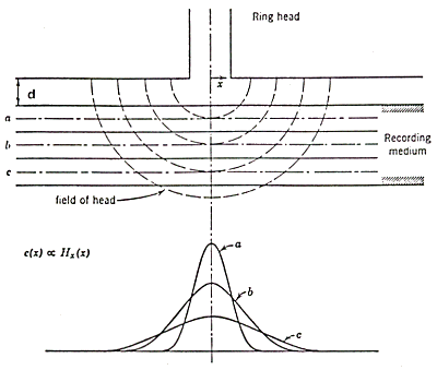
Fig. 3.4
From the discussion in chapter 2 we may derive that there
is a reciprocity between a current and a magnetic field. We have seen that
a coil in which a current flows produces a magnetic field, and that a moving
magnetic field is able to produce a current in a coil. If the permeability
of the core is very high, it is a valid approximation to state that the relative
permeability is infinite. Under these conditions we may think of the head
as a linear element, in which a current pulse is proportional to the field
that generated it. We can apply this "principle of reciprocity" in order to
better understand the behaviour of the parameters and their relations. For
example, what fig. 3.4 really shows is the shape of an electrical pulse e(t)
produced across the coil. For the principle of reciprocity, since e(t) is
proportional to H, we can think that the intensity of the magnetic field has
a similar shape.
It is important noting that H has a strong dependence on the
distance, even for small increases. Moreover, the pulse shape broadens, while
the intensity is decreasing. This means that without corrections, i.e. increasing
the current to give a stronger field, we have writing density limitations
if we raise the separation of the head from the medium or the thickness of
the coating.
Reading
The reading process is fundamentally ruled by Faraday's law.
For a coil made of N turns the electrical pulse induced is:
e(t) = - N D F / D t = - N v D F / D x
e(t) is a function of time and it depends on the variation
of the magnetic flux. This variation may be expressed in terms of the spatial
distribution of the magnetization in the medium and of the relative velocity
v between the medium itself and the head. This means that to be able to read
we must detect the changes in magnetization generated in the medium. The shape
of the pulse, its time dependency, is defined by the spatial distribution
of the magnetic field (fig. 3.5).
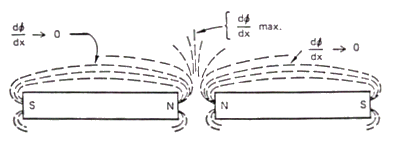
Fig. 3.5
The pulse will have a maximum in correspondence with the change
in magnetization at the border of a "bit" (the flux change is maximum here),
it will then decrease to a zero value while the magnetization becomes uniform
(one more approximation) in the rest of the magnetised region.
In the real world several factors, dependent on the geometry
of the configuration and on the materials, affect the pulse. First of all
a head has finite dimensions, this fact may be reflected in introducing an
efficiency factor a r.
The read efficiency is defined in terms of the reluctances of the parts composing
the magnetic circuit of the head:
a r = Rgap / (Rgap + Rcore)
From the definition of reluctance R = l / m s, if sc and sg are the cross sectional areas of the
gap and the core, and g and lc their length:
a r
= (g/sg) / [(lc/sc m c) + (g/sg)] = 1 / [1 + (lc sg / g sc m c)]
where m c is the permeability of the core and m (gap)
= m (air) = 1.
If the head has uniform cross sectional area, or the difference
between sc and sg is not too big (usually a good approximation):
a r = g / (g + lc / m c)
When the head is not completely saturated (this is usually
the case since complete saturation is only a mathematical abstraction) we
may assume that the read and write efficiencies have about the same value.
In order to describe the detected pulse, we now need to evaluate
the factor D F / D x.
In the ideal case we have a sudden and sharp inversion of
magnetic field between two adjacent zones. In the real physical world such
clear changes do not exist, we shall experience a continuous transition that
will take some small but non zero space to happen. A good approximation is
to think of a series of alternating bits as having a sinusoidal change in
magnetization, i.e.:
B(x) = Br sin (2p x / l )
where Br is the remanence of the material, and l is the wavelength of the recording pattern, i.e. the linear dimensions of
the bits along the track.
The expression for the pulse e(t) can be derived mathematically
from these assumptions and, in the early 50's, the dependencies of e(t) on
the geometrical parameters were confirmed experimentally. The relations are:
Thickness factor:
T(l ) = 1 -
exp (- 2p d /l )
Separation factor:
S(l ) = exp
(- 2p d/l )
Gap length factor:
G(l ) = [sin
(p g/l ) / p gl ]
where d is the thickness of
the medium, d the distance between head and medium (flying height) and g the
gap length.
A better approximation for G(l ) is obtained by multiplying it by the quantity:
[5-4(l /g)2 / 4-4(l /g)2]
It was also found that these factors are independent. This
means, for example, that if we vary the flying height d, having fixed all
of the other variables, the value for e(t) will change according to the expression
S(l ). Thus the expression for the pulse induced
is:
e(t) = 10-8 N W a r (m / m +1) v Br T(l ) S(l ) G(l ) cos(2p vt/l )
where :
a r = head read efficiency
N = number of turns of the coil
W = track (or head) width (cm)
m = head
core permeability
v = velocity (cm/s)
Br = medium remanence (G)
l = bit
length on the track (cm)
e(t) is in Volt if all the other quantities are
in cgs units.
For constant velocity, as a function of frequency (f = v/l ) the peak output would follow a curve like in fig. 3.6.
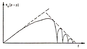
Fig. 3.6
At very low frequencies (low rate of flux change) the amplitude
of the pulse is smoothly increasing. After having reached a maximum, depending
on all the parameters seen above, the peak output has a marked decrease, mainly
due to the separation factor and to the gap length factor, if it is very long
with respect to the spacing.
The sinusoidal change in magnetization, as stated before,
is an approximation. A better representation is given by the so called arctangent
transition. The magnetic field is supposed to change according the law:
B(x) = - (2 Br / p ) tan-1(x/a)
This type of transition is shown in fig. 3.7.

Fig. 3.7
The quantity a is the slope of the curve in the region of
the change, its value depends on the magnetic characteristics of the medium
and on its thickness:
a = Br d / 2p Hc
(Hc is the coercivity of the medium).
It can be noted that the ideal step transition is a special
case of an arctangent transition (when a = 0).
The expression for e(t) that can be derived is, obviously,
more complex. However, the sinusoidal approximation gives a very good agreement
with the experimental measurements. Moreover, if the recorded density is very
high, the sinusoidal expression becomes again a valid approximation of the
real situation (perhaps better than the arctangent).
We can suppose that the pulse induced in the coil has a bell
shape (fig. 3.8). If this is true, we need two parameters to define completely
the curve: the maximum amplitude (the expression given above for e(t)) and
its half height width. The latter may be calculated and has the value:
PW50 = (g2 + 4(d+a) (d+a+d ))1/2

Fig. 3.8
This value depends only, with the exception of a, on geometrical
parameters. It may be seen as a measure of the resolution of the system.
We are now able to understand the effects of the variation
of any parameter on the amplitude and on the "width" of the pulse across the
coil. Since, as we saw, the effects are independent, at least to a first approximation,
we may examine them separately. Figure 3.9 shows the effect of a spacing (flying
height) variation.
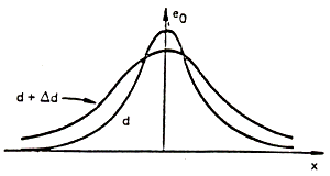
Fig. 3.9
By increasing the spacing, the amplitude of the signal decreases
and the pulse broadens and we get worse resolution. Since d and a appear together
in the expression for PW50, the same effects happen for variations in a, i.e.
for variations in the magnetic characteristics of the medium.
For small changes in the thickness of the magnetic coating,
the amplitude increases and the pulse broadens (fig. 3.10). This, like any
other broadening of the pulse, is a loss of resolution, or a need for a decrease
in the recording density.
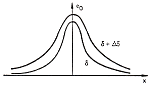
Fig. 3.10
The gap variations are more complicated. Ignoring the efficiency
of the head, the amplitude depends on g as shown in fig. 3.11.
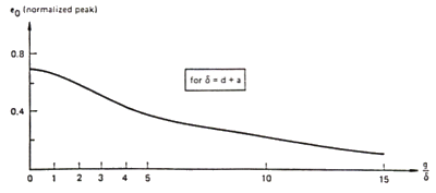
Fig. 3.11
If we introduce the parameter a (efficiency), we should remember that it is a function of g.
In some cases, for particular geometries, the pulse may increase
in value over some range of dimensions before decreasing. In any case the
pulse broadens with increasing the gap (fig. 3.12).
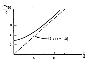
Fig. 3.12
Variations in any other quantity, such as number of turns,
head width, velocity, produce changes in amplitude only.
Some of these variations may have different effects. Let us
make an example. One might conclude that, in order to increase the peak value
for the pulse, it is possible to increase the number of turns in the coil
(e(t) depends linearly on this quantity). Now, a series of quickly alternating
pulses may be seen as an alternating current and since the materials with
which a head is made are usually good conductors, we can see the head as an
electrical circuit in which an alternating current is flowing. Thus, we can
apply the laws that rule these kind of circuits. The intensity of current
will be given by:
I(t) = I0 exp (- (R/L) t)
where R is the resistance and L the inductance of the circuit.
The main effect of the inductance is to produce a time delay
on the current. The quantity L/R is called time constant of the circuit. A
time of about 5 (L/R) is needed before reaching 99% of the current. The inductive
part of the circuit we are considering is the coil encircling the head core.
The inductance of a coil is mainly due to its geometrical characteristics:
length of the coil, number of turns, dimensions of the wire, diameter of the
coil, spacing between the turns. This means that changing the physical parameters
of a coil, we change its inductance, this change is reflected in a variation
of the time constant of the circuit and in a variation of the delay with which
the current will reach its maximum. If we introduce a delay in the current,
we delay the magnetic field produced as well. This will be reflected in a
lower magnetization of the medium, or in an increase of the linear dimensions
of the bit cell, thus affecting the detected pulse.
Pulse superposition
All the considerations made so far were made taking into account
a single, isolated pulse. What we really have is a series of magnetic transitions
that appear, after having read them, as an alternating series of positive
and negative pulses. The basic phenomenon we should investigate is the composition,
and the reciprocal interferences, of a pattern formed by this series of transitions.
If the readback process is, at first approximation, a linear
process, we may sum algebraically the head response of every single transition
of the series. The total response will depend on the distance between the
isolated pulses (bit spacing). In fig. 3.13 is shown the result of the composition
of two adjacent saturation reversals.
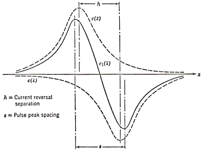
Fig. 3.13
The important effect of this linear composition is that the
resulting pattern has a decrease in the peak amplitude and a shift of the
peak position. The output amplitude approaches zero as the bit separation
h becomes very small. With four reversals the resultant configuration is depicted
in figure 3.14.
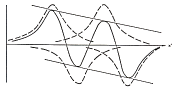
Fig. 3.14
The net result is not only peak decreasing and shift, but
also a droop in the shape of the resulting waveform.
The total composition effect is perhaps the most important
limiting factor on the maximum bit density that is obtainable from a given
configuration. If we sum a long series of pulses, plotting the value for the
resultant e(t) vs. the bit density, we obtain figure 3.15.
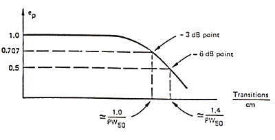
Fig. 3.15
In the figure the points are shown in which the attenuation's
of the pulse are 3 and 6 dB. The second one represents a reduction to one
half of the peak value of an isolated pulse (e(t) = PW50).
It is important to note, at this point, that we have not mentioned
that in any electrical circuit there is an unpredictable noise that may seriously
affect the possibility of obtaining a meaningful readback signal.
From a physical point of view, the interferences between adjacent
pulses may be seen as interferences between the magnetic fields of the single
bits. For a single magnetised region, the head "reads" the field due to that
region. Since the dimensions of the bit are finite dimensions, even if small,
the field due to an adjacent region will receive a contribution from the previous
one. The resulting field read will be, therefore, different from that due
to a single bit. Its intensity, if the bits are opposite, will be lower and
its modified shape will displace the point of maximum flux change thus leading
to a modification in amplitude and shape of the detected pulse.
4 - Conclusion
In a commercial storage device we are interested in having
high capacity and good performance. We have seen that the density is the main
parameter we must deal with for its influence on performance. It is possible,
with the formulas and the approximations given, to find the theoretical limit
for the density of flux reversals in a storage medium. The main limiting parameter,
from a theoretical point of view, is a self demagnetisation factor that arises
when the bit spacing is too small. In other words, the magnetic interference
between adjacent bits may be so high that it becomes impossible to recognise
the single magnetic transitions. It may be shown that the limit for the linear
length (in cm) of a magnetic transition is given by:
l = Br d / 2 Hc
where d is the medium thickness
(cm), Br is the remanence of the medium (Gauss) and Hc its coercivity (Oersted). For a given material, the density limit is depending
on its magnetic properties and on the coating thickness. The theoretical limit
for known materials and for known, even if by now not yet achieved, techniques
is of the order of magnitude of 1010 bits per square inch.
The relations given and the considerations made may help us
in better understanding the properties and the behaviour of a storage device.
They may also let us understand some of the reasons behind certain choices
or technical solutions adopted in a machine. For example, let us consider
a magnetic disk. A head is usually flying over a spinning disk sustained by
the air flow generated by the moving surface. The head disk separation will
not be constant across the radius of the disk. In fact, assuming constant
rotational speed, on an outer diameter the linear velocity is higher than
on an inner diameter. Thus we can assume that the air flow generated has higher
intensity and the separation increases toward the border of the disk. Now,
if the separation increases, the amplitude of the detected current pulse decreases
and the pulse itself broadens. On the other hand, the amplitude loss may be
compensated by having a higher thickness of the coating on the outer regions
of the platter. This fact produces again a pulse broadening. To gain in resolution
we must have a higher spacing between the bits.
Therefore we are able to understand that, in order to get
a pulse uniform in amplitude and in shape, a magnetic disk would have a variable
coating thickness and a constant number of bits per track.
This one and other qualitative conclusions may be derived
from the formulas and the considerations made so far. It could be quite impossible
to get exact quantitative results for a given set of materials.
Even if we could remove some of the approximations we made
and solve the very complex equations, the real situation has too many parameters
and too many relations between them to succeed in having a full theoretical
description of this phenomenon.
5 - Bibliography
Alonso, M., Finn, E.J., Fundamental University Physics,
Addison Wesley, Reading, MA, 1967.
Anderson, H.L. ed., Physics Vademecum, Amer.
Inst. of Physics, 1981.
Hoagland, A.S., Digital Magnetic Recording, Wiley,
New York, 1963.
Jackson, J.D., Classical Electrodynamics, Wiley,
New York, 1975.
Karlquist, O., Calculation of the Magnetic Field
in Ferromagnetic Layer of a Magnetic Drum, Trans. Royal Inst. of Tech.,
Stockolm, 1954, vol.86,1.
Landau, L., Lifchiz E., Theorie des Champs, MIR,
Moscou, 1970.
Milford, F.J., Reitz, J.R., Foundations of Electromagnetic
Theory, Addison Wesley, Reading, MA, 1967.
Wallace, R.I. Jr., The Reproduction of Magnetically
Recorded Signals, The Bell Tech. Journ., Oct. 1951.
IBM Journal of Research and Development, 1974, vol.18,
n.6.
IBM, Disk Storage Technology, 1980.
(Figures 1.1, 2.2, 2.6, 3.2, 3.3, 3.4, 3.13 are from Hoagland, Digital Magnetic Recording)
Rodolfo
Baggio, Introduction to Digital Magnetic Recording,
IBM Customer Executives
Briefing Center, Mainz,
Germany, October,
1986
|


